So you’re ready to take your one-of-a-kind invention to the next level. First of all – congratulations! Second, let’s talk a little bit about one of the most important things to know about your design; what views your drawings are going to need in order to make sure that your patent is fully covered and protected.
We understand that navigating through all the requirements for a design can be a little overwhelming if you’re new to the ways of the patent illustration world. And to stress you out a little more, if you plan to file internationally – WIPO can be very (and we mean very) picky when evaluating your drawings.
But no need to fret just yet! We could just copy-paste the USPTO’s text on Design Patent Views, but that’s too easy and seemingly everyone that calls themselves a patent draftsperson is doing just that. Instead, I’ll review what the patent office says and then I’ll tell you what that means to me.
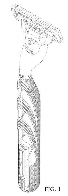
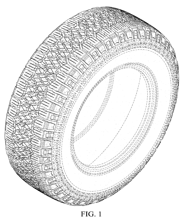
It could also be a design or pattern applied to a surface, such as the tread of a Kenda tire (yes, IP Illustration prepared the figures for this design patent, too). It’s important to note that design patents are not intended to protect an item’s “structural or utilitarian features”.
The Seven Standard Views + An Additional View
The views themselves are very simple and while they can be shown in any order, I recommend that they follow this convention:
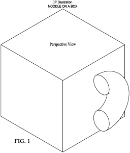
FIG. 1 – Perspective View
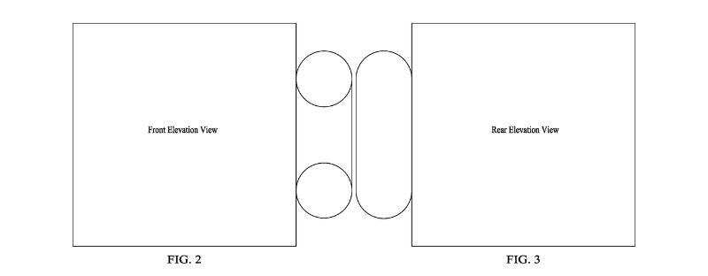
FIG. 2 – Front Elevation View
FIG. 3 – Rear Elevation View
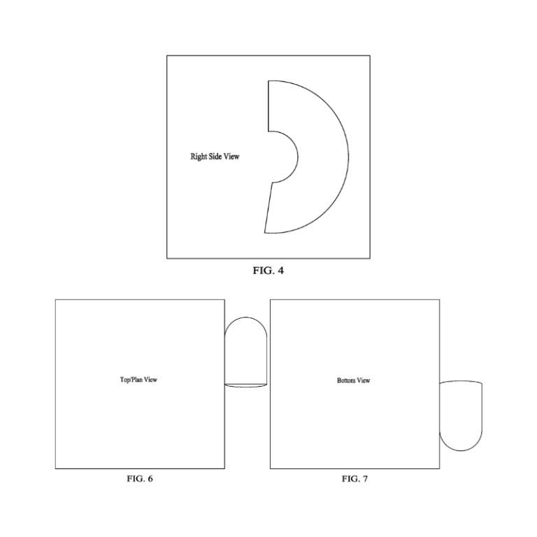
FIG. 4 – Right Side View
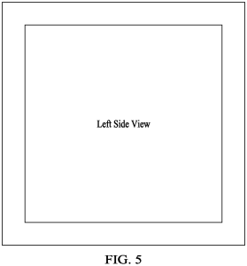
FIG. 5 – Left Side View
FIG. 6 – Top/Plan View
FIG. 7 – Bottom View
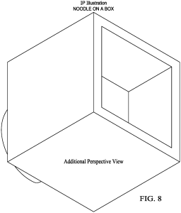
FIG. 8 – Additional Perspective View
Why so many views?
Why not just replace some of the views with fancy words, such as “FIG. 5 is a mirror image of FIG. 4”? Beyond the words used to briefly describe the figures (brief figure description) and a statement that describes the use of broken lines (more on broken lines in the next blog post), the drawings alone make up the visual disclosure of the claim (see section 1503.02 of the MPEP). Yes, in the world of design patents, a picture is worth a million words.
Why not go with fewer views and just add more later?
This is a lot of information to digest, so let’s take a look at the views in action with an example. We will use IPI’s greatest invention, “Noodle On A Box”™.
FIG. 1: Top Perspective view.
As you can see below – the top, front, and right side surfaces are shown, as well as the noodle. Perspective views are very important as they illustrate depth and contour not seen in straight on orthogonal views. Orthogonal views are two-dimensional views created from a three-dimensional representation (we’ll get more into that later).
FIGS. 2, 3, 4, 6 and 7 are generally pretty straightforward as they don’t introduce any matter that can’t be seen or supported in FIG. 1, the perspective view.
If you’re paying close attention, you’ll notice that I skipped FIG. 5 in my list of figures above. Why?
The left side view, shown below in FIG. 5, illustrates a second square within the larger outer square. What we can’t tell “without conjecture” is the nature of this inner square.
Is it surface ornamentation?
Is it recessed?
If yes, how deep in the recess?
In this example, the inner square is intended to illustrate a recess. To properly disclose this in the Design Patent Application we will add a FIG. 8, which will be an additional perspective figure as shown below.
In this illustration we clearly show the inner square and the implied depth of this recess. Crisis averted! All features that make up the IPI Noodle on a Box have been fully and completely enabled.
Will this design pass examination by a patent examiner? Not yet. Stay tuned for the second part of this blog to learn why, and what can be done to avoid a rejection.